Have you ever wondered how IoT and other hardware manufactures debug and test their devices. Well, most of the time they leave serial interfaces that they can hook into to read real-time debugging logs or interact via a shell. There are a couple different serial interfaces, but one of the most common ones is the Universal Asynchronous Receiver-Transmitter (UART).
On this tutorial we will discuss how to connect via UART to the TP-Link WR841N (version 9.0) using the Attify Badge. This write-up is a loose follow-up on the previous 5-Min Tutorial on lifting firmware with the Bus Pirate, so you might want to check that out first (but it's not required).
* Recently revived my old Twitter account. Follow me for more hacking content!
Follow @konukoii
UART
Before proceeding I wanted to go a little bit more in-depth of what UART is and how it works. Feel free to skip this part if you just wanna get to the hacking!
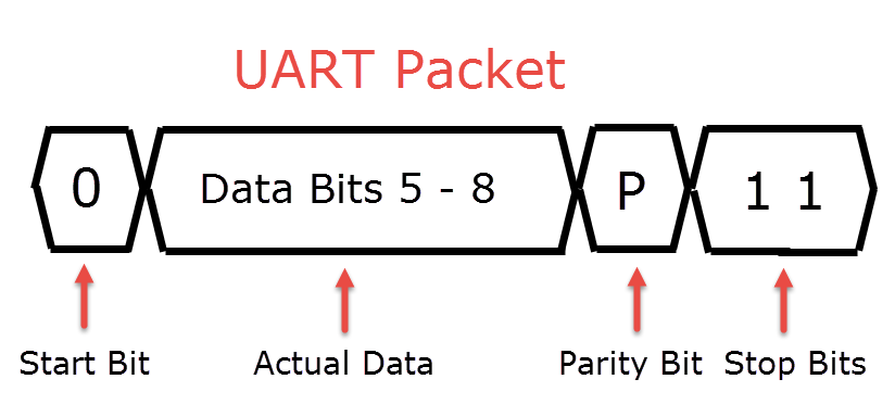
UART refers to Universal Asynchronous Receiver / Transmitter. It is a serial communication interface that doesn't depend on a clock (unlike other serial interfaces). It can be anywhere from simplex (one directional communication), half-duplex (devices take turns transmitting), or full-duplex (both devices can communicate at the same time). The communication itself is done via packets:
Finding the UART Ports
The UART ports on the physical device are usually found as a line of 3/4 pins or pads next to each other. In the case of the TP-Link WR841N (version 9.0) we can see them as 4 pads as shown below:
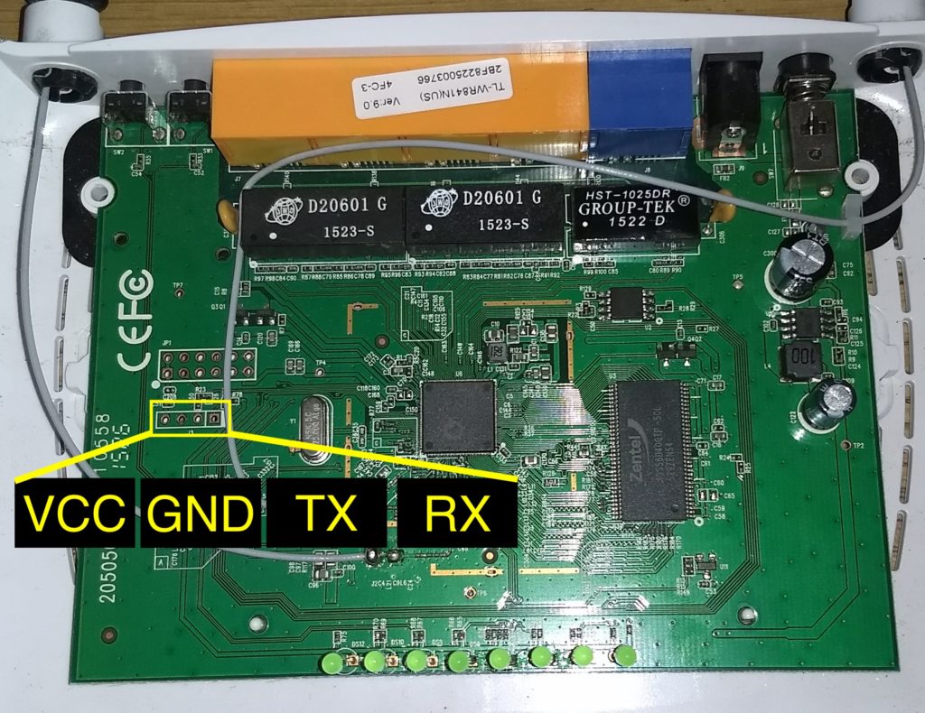
Once you find the UART ports we have to distinguish each pin (GND, VCC, TX, RX). To do this we have to follow the next steps:
- Identifying GND: Turn off device. Place your multimeter in Continuity mode (The dot with three semi circles to the side) Place the black probe on Ground Surface (Any metallic surface on the board - e.g Ethernet shield). Place the red probe on each of the four pads, when it beeps you'll know thats GND.
- Identifying VCC: Place the Multimeter on DC Voltage (V-). Place black probe on GND and use Red probe to check UART pins. Power Cycle the device, the place where you see a constant high voltage is our VCC Pin. (Hint: It'll be close to either 3.3V or 5V)
- Identifying TX: Once you know VCC and Ground, TX is the pin that hast the biggest fluctuations in voltage during the initial 10-15 seconds of boot-up. This is because a lot of information is transmitted during boot-up.
- Identifying RX: RX can be determined by the pin having the lowest voltage during the entire process. Otherwise it is the last pin remaining.
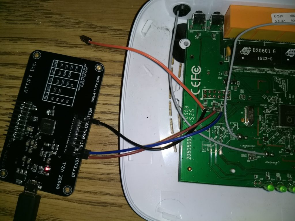
Now that we have identified all the proper ports, you can solder some connectors to it and hook it up to the Attify Badge as follows:
| TPLink | Attify Badge |
| GND | GND |
| TX | D0 |
| RX | D1 |
| VCC | - None - |
Interacting with UART
Before we actually start communicating with the UART ports we need to find the Baud Rate. The Baud Rate is the rate at which data is transferred between the devices. In other words the # of bits per second. Some common baud rates can be 9600, 38400, 19200, 57600, 115200, but theoretically it can be whatever the manufacturer wants.
We will use devttys0's python script to quickly find the proper Baud Rate.
$ git clone https://github.com/devttys0/baudrate
$ cd baudrate
After downloading the tool, we will connect our TP-Link to power and we will want to power it on and at the same time run the script.
$ sudo python baudrate.py
Afterwards you can use your up and down keys to scan through different baud rates, as if you where tuning into a radio station. Scroll until you start seeing a bunch of debugging statements. If you don't see anything, try turning power on/off, as most devices will spit out large quantities of debugging statements during bootup.
In our case, the TP-Link router is using a baud rate of 115200.
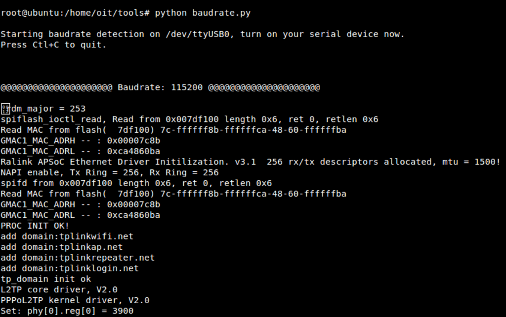
To interact with our device via UART, we can simply run:
screen /dev/ttyUSB0 115200
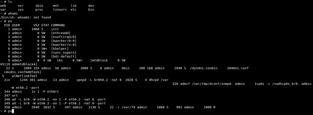
Boom! we have root shell access! You can now look around or modify the filesystem any way you wish!
Unexpected Surprises!
These are some interesting behaviors I witnessed during my experiments:
TP-Link Dumbing Down their Security!
Recently I did some experiments on both the TP-Link WR841N v.9 and v.20, and I found a surprising behavior. On the v.9 router when you try to access a shell via UART, you are asked for a login/password. Instead on v.20 you are given free reign on the shell!
I have no idea why TP-Link would purposely degrade the hardware security level on their own routers?!
UART + First Boot-up = No Go
So I noticed this interesting behaviour were if you hook everything up to UART and try to boot up for the first time, the router won't actually start. Instead you have to take out the TX/RX cables and once you hit the power actually reconnect. This gave me an interesting look at the very first boot-up sequence.
Here you can see interesting moments such as the creation of Dropbear rsa/dss keys:

If you are curious and want to look at all the dump feel free to download it from here: tp-link-bootup-konukoii.txt
I am uncertain why this happens, or how they even check if something is hooked up to UART. If anyone has any ideas please let me know; I really would love to know!
Further Research
My main goal now is to create backdoors in these routers either by creating malicious firmware or modifying certain files via UART. I'll also continue investigating what other changes have happened between the two router versions, but for now I hope this has been an interesting read and, as always, feel free to hit me up with any question or comments. Keep on Hacking!
Another awesome post! Thanks for the great writeup